DUOYI
DUOYI DY5500 4 in1 Digital Fluke Multifunction Insulation & Grounding Resistance Tester Voltmeter Measuring Phase Indicator
DUOYI DY5500 4 in1 Digital Fluke Multifunction Insulation & Grounding Resistance Tester Voltmeter Measuring Phase Indicator
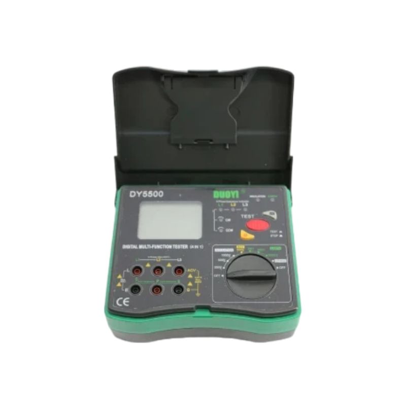
DUOYI DY5500 4 in 1 Digital Multi-function Tester
Insulation Tester + Earth Tester + Voltmeter
+ Phase Indicator 0.01ohm to 2000ohms
The brand DY5500 multi-functional instrument can measureearth resistance, insulation resistance, AC voltage and phase sequence. As a new generation electrical measurement instrument which we have successfully developed recently.It is aimed by the nice and fashionable design,more stronger functions that easier to use and more reliable. The instrument and accessories are all in the tool box . It can be used to test the insulation resistance and earth resistance of power system, electrical equipment, lightning arrester equipment,and measure AC voltage and phase sequence test.
Features:
Ground resistance measurements from 0.01ohm to 2000ohms with 0.01ohm resolution.
Measure insulation resistance to 2000M ohms.
Test voltage 250V, 500V, 1000V.
AC voltage measurement to 600V.
Check phase sequence and phase status.
Auto ranging, data hold, LCD backlight.
Low battery warning.
Complete with test leads, auxiliary earth bars, phase wire, heavy duty carry case and eight AA 1.5V dry cells
Low power consuming CMOS dual integral A/D ,conversion IC, automatic zero.
Environment conditions:
Operating temperature: 0C~40C
Relative humidity<80%
Storage temperature: -10C ~50°C
Relative humidity<80%
PANEL INTRODUCTION

1.LCD
2.Phase sequence measurement LED indicators (CW CCW,L1, L2and L3)
3.Insulation resistance measurement high voltage LED indicator
4. Earth resistance measurement LED indicator
5.Data holding button
6.Test button
7. Back-light button
8.Function rotatory selector
9."E/G" Earth resistance“E”input terminal / ACV measurement/ COM terminal/insulation“G”input terminal for shield
10.Earth resistance “P”input socket
11.Insulation“E”input socket
12.“C/L1/ L”earth resistance“C”input terminal / phase sequence“L1”input terminal/ Insulation"L”input terminal
13."L2 "phase sequence input socket
14.“ACV”Input socket /Phase sequence“L3”input socket
Electrical Specification
1.Insulation Resistance
|
Testing Voltage |
250V / 500V / 1000v |
|
Output Voltage |
90%-110% of the test voltage |
|
Range |
0.1MΩ-20GΩ |
|
Resolution |
0.01MΩ |
|
Accuracy |
0.1MΩ-200MΩ±(3%rdg+5dgt) |
|
200MΩ-20GΩ±(5%rdg+10dgt) |
2. Earth Resistance
|
Range |
Accuracy |
Resolution |
Test Frequence |
|
20Ω |
±(2%rdg+0.1Ω) |
0.01Ω |
Approx.820Hz |
|
200Ω |
±(2%rdg+3dgt) |
0.1Ω |
|
|
2000Ω |
1Ω |
3.AC Voltage ( Earth Voltage) Measurement
|
Measurement range |
1-600VAC |
|
Accuracy |
+(2% rdg+ 5dgt) |
|
Resolution |
1V |
|
Test frequency |
40-400Hz |
4.Phase Sequence Test
|
Measurement range |
100V-450V |
|
Accuracy |
+(2% rdg+ 5dgt) |
|
Frequency |
50-60Hz |
Note: Phase sequence test result is indicated by LED, NO display in LCD.
Earth Resistance Measurement
3-Wire Earth Resistance Test Method
a. Earth Voltage Measurement
Put the auxiliary earth spikes P1 &ACV1 into the soil 5 to 10 meters away from the object under test in straight distance as shown in Fig 1,connect the green wire to theterminal “E”of the instrument, yellow wire to the terminal “P” and red wire to the terminal "ACV".
Turn the rotatory selector to 600V AC position firstly and confirm this voltage is lower than 10V. If the voltage is higher than 10V, there will be error in the measurement value of the earth resistance. In such case, power off the earth electrode under test to reduce the earth voltage before you test again.

E is connected to the port of earth electrode
P is connected to the port of potential electrode
ACV is connected to the port of voltage electrode
Notice: Be sure to insert the auxiliary earth spikes into soil with high water content. In case of the soil is dry, has many sands or gravels,be sure to add water to ensure the soils in which auxiliary earth spikes are inserted are wet. In case of cement land, place the auxiliary earth spikes horizontally and add water, place wet towels wrapping the auxiliary earth spikes before you test.
b. Earth Resistance Measurement
b-1. Test Wire Connection
Put the auxiliary earth spikes P1 and C1 into the soil5to 10 meters away from the object under test in straight distance as shown in Fig2,connect the green wire to theterminal “E”of the instrument, yellow wire to the terminal “P” and red wire to the terminal “C”
E is connected to the port of earth electrode
P is connected to the port of potential electrode
C is connected to the port of current electrode
b-2. Connection Inspection
Press the“Test/Stop” button, Ifthe“Ok” indicato on the LCD is light, it indicates that the wires are well connected to“P”and“C”terminals,and the earth resistance of the auxilliary earth spikes is within the allowed range. If the“OK" indicator on the LCD is not light, check the wires connected with“P”and“C" terminals or reduce the auxiliary earth resistance to an appropriate level by changing the position of earth-spikes or wetting the soil. You can short circuit the clamps in red and yellow wire terminals to check if they are broken.
b-3. Measurement Operation
Rotatory selector set to 20008 press the“ Test/Stop” button,if the displayed value is too small,switch to 2009 or 209. The value displayed now is the resistance of the earth resistor.
Notice: Be sure that no wire twists with any other wire. Twisted or not well connected wires generate induction in testing and impact readings. If the auxiliary earth resistance is too big, some errors are generated. Be sure that auxiliary earth spikes are inserted into moist soils, to ensure the various parts are in full contact.
2-Wire Simplified Earth Resistance Test Method
This test method is intended for the application where cann't inserting an auxiliary earth spikes . In this method,an existing earth electrode with very lttle earth impedance is used, such as a metal water pipe, a common earth of a commercial electric power system, or a earth terminal of a building instead of the auxiliary earth spikes“C” and “P".
a. Test Wire Connection
Connect wires with simplified test wires as shown in the figure above.
Danger: be careful of electrical shock when you use the commercial electronic system earth method. Do not use this instrument to testthe voltage of power supply.
b. Earth Voltage Measurement
Be sure to set the range selector to the 600VAC , and confirm the voltage is lower than 10V. If the voltage is higher than 10V,power off the earth electrode under test to drop the earth voltage before you
test again. .
c. Earth Resistance Measurement
Start from 20000,press the“Test/Stop” button, the“OK" indicator on the LCD will turns on, indicating the test is in process. In case of the value displayed is too small, switch to 2000 or 200 for measurement.The value displayed now is the valueof the earth resistance.
Notice:
The measurement current is approx. 2mA. Therefore, even if a RCD is connected, the RCD will not act. The real earth resistance RX must be calculated with the formula below:
RX=Re-re .
Re: reading of instrument
re: earth resistance of common earth terminal of commercial power system
PRODUCT DETAILS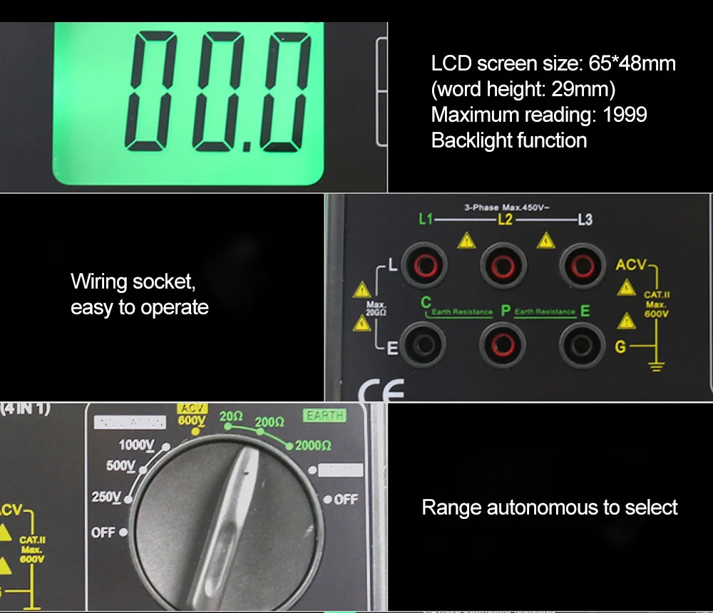

FEATURES & SPECIFICATIONS
Specifications
-
MODEL : DY5500
-
Earth Resistance: 0~20/200/2000 ±(2%+5)
-
Testing Voltage: 250/500/1000V
-
Insulation Resistance : 0.1~2000M ±(3%+5)
-
Phase Rotation Check: yes
-
AC Voltage : 700V ±(2%+5)
-
Auto Range: yes
-
Function Symbol Display : yes
-
Data Hold : yes
-
Low Battery Warning : yes
-
Max. Displays : 1999
-
LCD Backlight : yes
-
Product Size: 190 * 155 * 75 mm
-
Power: AA1.5V x 8 (not include in the package)
Accessories
Packing list:
1. User Manual *1
2. Tool Case* 1
3. Phase Sequence Test Wire* 1
( Green and Red )
4. Insulation Resistance Test Wire *1
( Red Lead with Big Probe / Black Lead with Big Clip / Black Lead with Detached Little Clip )
5. Earth Resistance Test Wire *1
( Red 15-meter Test Wire / Yellow 10-meter Test Wire / Green 5-meter Test Wire )
6. Simple Earth Resistance Test Wire* 1
( Red 1.6-meter Test Wire /Green 1.6-meter Test Wire )
7. Auxiliary Earth Spike *2
8. 1.5V( R6P) AA battery *8(not include)
9. Tool Bag *1